Marsh Hydroil Bypass separators

A Bypass Oil Separator is used in a ‘low risk’ environment where there is no requirement to provide full treatment for the flow: for example a car park where the risk of a significant spillage is small.

Designed and tested to BS EN858 parts 1&2, Marsh Hydroil bypass separators are manufactured from virgin unfilled resin offering exceptional durability, impact resistance and are guaranteed to be watertight and of uniform thickness. These combined properties ensure that the full range of separators stand up to the most rigorous conditions during their service life.

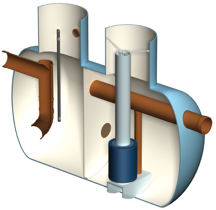
Internal working components, such as coalescing filters, weirs, oil skimmer plates, and their configurations offer the most modern and efficient oil/water separation capability available to the market today.

A wide choice of inlet and outlet positions are available on the units – detailed requirements should be provided at time of order (standard inlet and outlet positions will otherwise be fitted).

Typical applications

  • Car parks
  • Roadways
  • Industrial estates
  • SuDS


Operating principle

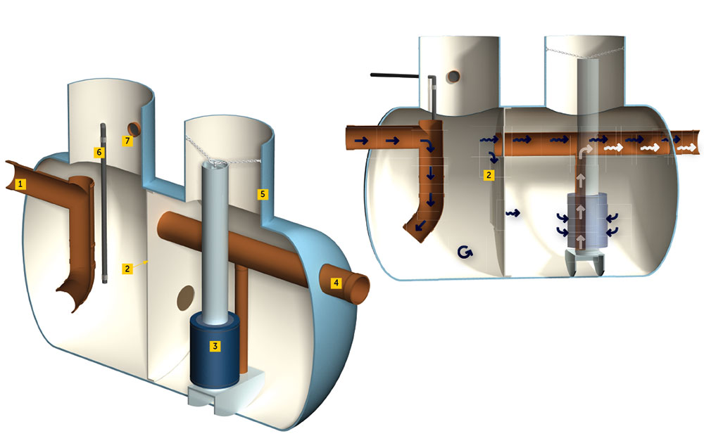
Marsh Hydroil bypass separators are designed to treat 10% of peak flow.

The drainage areas served by each separator are determined in accordance with both BS EN858 parts 1&2, but also with reference to a formula provided by the Environment Agency, where NSB=0.0018xA (catchment area in m2). Flows from higher rainfall rates are allowed to bypass the main separation chamber.

KEY

  1. Inlet
  2. Oil skimmer plate
  3. Coalescer
  4. Outlet

5. Access turret

6. Level alarm dip pipe

7. Air vent

FLOW PATH

hydroil bypass oil separator flow


Benefits

  • Designed and tested to meet latest UK and European standards
  • Corrosion resistant
  • Tank shells guaranteed for 25 years with a design life of 50 years
  • Heavy duty shells enable installation in all ground conditions
  • Easy access turrets for maintenance and servicing (Turret guards optional)
  • Various alarm types available (Required by EN858-1)
  • Variable invert depths and inlet/outlet configurations ­­­to suit individual site conditions
  • Vented turrets dissipate excessive fumes and vapours

Specifications

Model Max flow (litre/sec) Drainage area (m2) Silt storage (litres) Oil storage (litres) Width +/-50mm Length +/-50mm Height +/-50mm Connection size Inlet invert Outlet invert
NSBP 3 30 1700 300 45 1354 2254 1834 160 900 950
NSBP 4 45 2550 450 67.5 1354 2254 1834 160 O/D 900 950
NSBP 6 60 3400 600 90 1354 2254 1784 200 O/D 900 950
NSBP 8 80 4530 800 120 1354 2254 1784 200 O/D 900 950
NSBP 10 100 5660 1000 150 1354 2914 1784 315 O/D 900 950
NSBP 15 150 8510 1500 225 1354 4184 1784 315 O/D 900 1000
NSBP 18 180 10198 1800 270 1818 2398 2418 400 O/D 1050 1150
NSBP 20 200 11370 2000 300 1818 2398 2418 400 O/D 1050 1150
NSBP 25 250 14185 2500 375 1818 3198 2418 400 O/D 1050 1050
NSBP 30 300 17000 3000 450 1818 3758 2418 500 O/D 1185 1285
NSBP 40 400 22650 4000 600 1818 4878 2418 500 O/D 1185 1285
NSBP 45 450 25325 4500 675 1818 5438 2418 500 O/D 1185 1285
NSBP 50 500 28330 5000 750 1818 5998 2418 500 O/D 1185 1285
NSBP 60 600 33996 6000 900 2622 4028 3172 600 I/D
Twin wall
1350 1450
NSBP 65 650 36829 6500 975 2622 4303 3172 600 I/D
Twin wall
1350 1450
NSBP 70 700 39620 7000 1050 2622 4578 3172 600 I/D
Twin wall
1350 1450
NSBP 75 750 42495 7500 1125 2622 4908 3172 600 I/D
Twin wall
1350 1450
NSBP 80 800 45330 8000 1200 2622 5415 3172 600 I/D
Twin wall
1350 1450
NSBP 100 1000 56660 10000 1500 3128 4702 3678 600 I/D
Twin wall
1525 1625
NSBP 125 1250 70820 12500 1875 3128 5741 3678 TBC* TBC* TBC*
NSBP 130 1300 73658 13000 1950 3128 6028 3678 TBC* TBC* TBC*
NSBP 150 1500 84990 15000 2255 3128 6780 3678 TBC* TBC* TBC*